
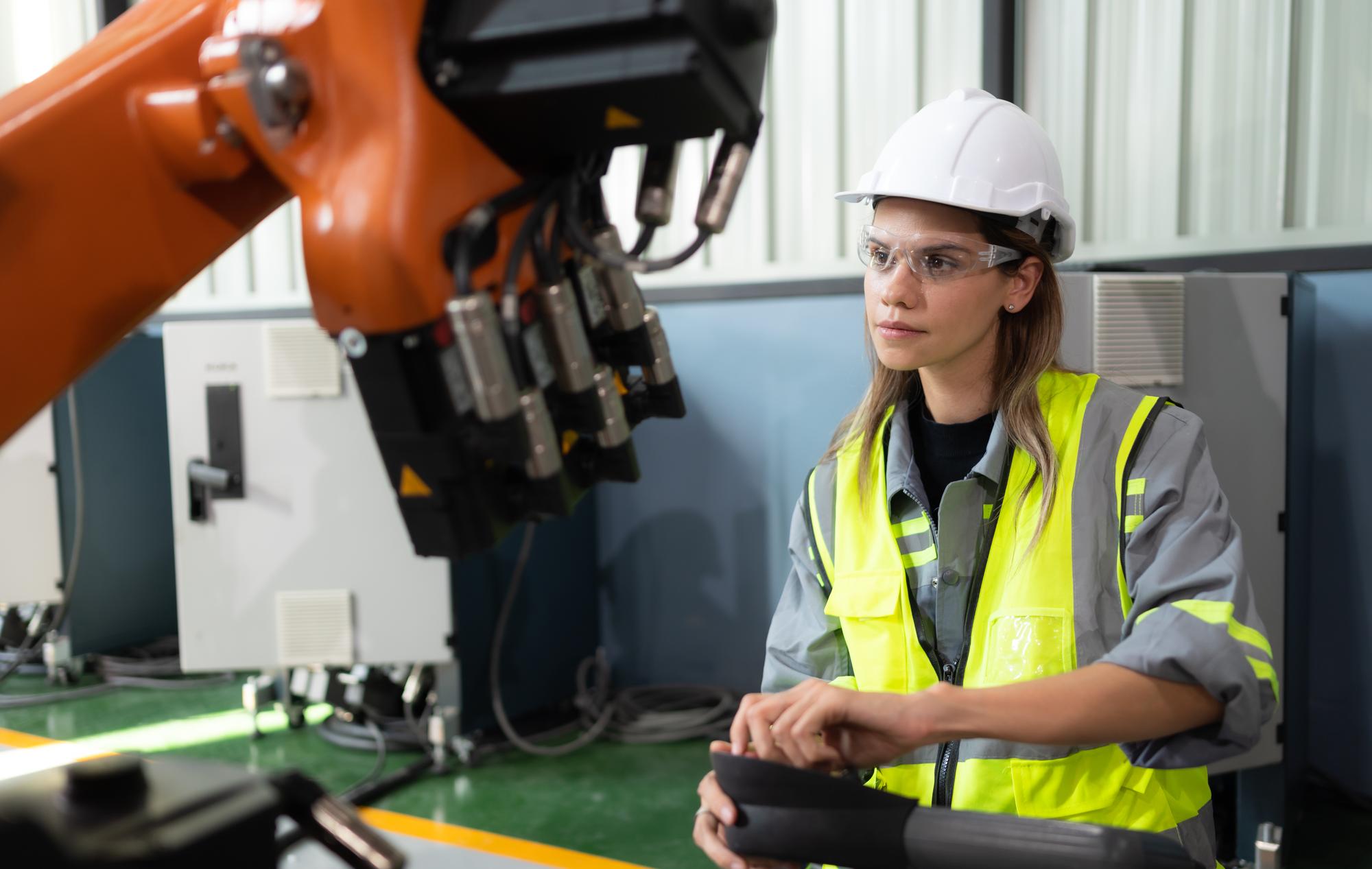
Build physical hardware for robots, UAVs and automated equipment without committing to production tooling too early. Excel Rapidtech supports robotics companies, drone developers, system integrators, research teams and factories with 3D printing, CNC machining, vacuum casting, reverse engineering and post-processing for prototypes and low-volume components.
Upload your CAD assembly and describe the load, movement, environment and test objective to request a process recommendation.
What is robotics prototyping?
Robotics prototyping is the iterative manufacture of mechanical parts and assemblies used to test motion, packaging, sensing, gripping, structural behaviour, operator interaction and manufacturability. It connects digital mechanisms, electronics and software with real components that must move together reliably.
In robotics, a small mechanical change can affect the whole system. Moving a sensor alters its field of view. Thickening a wall changes mass and motor load. Re-routing a cable affects joint travel. Changing a gripper finger influences contact and force. Rapid manufacturing lets teams test these interactions before ordering moulds, castings or larger machined batches.
The Government of India’s National Strategy on Additive Manufacturing describes AM as a next-generation digital manufacturing capability and promotes links among research, design and indigenous product development. Read the official strategy announcement. Robotics and automation teams are natural users of this flexible model because their hardware evolves through repeated integration cycles.
Robotics, drone and automation products we can help develop
Robot bodies and protective housings
Service robots, mobile robots and industrial systems need covers around electronics, drives and mechanisms. Candidate products include outer shells, controller housings, battery covers, motor guards, sensor pods, display bezels and service panels. SLA can support smooth styling models, while SLS or MJF can produce durable nylon development parts with integrated clips, cable paths and mounting features.
End effectors and gripper components
Grippers often require custom fingers, pads, brackets, vacuum-cup mounts, sensor holders and quick-change interfaces. Additive manufacturing enables shapes that conform to a workpiece and can reduce the mass at the end of a robot arm. CNC machining may be needed for high-load interfaces, wear surfaces or specified metal parts. Actual payload, acceleration, cycle count and failure consequences must be considered.
Drone and UAV components
Drone teams may require payload enclosures, camera gimbals, sensor mounts, battery trays, landing-gear concepts, antenna supports, fairings, ducting and protective covers. SLS and MJF can support complex lightweight polymer parts. CNC can support metal brackets and precision interfaces. Flight use requires design authority evaluation, testing and compliance; a successful print is only one part of that process.
Autonomous-mobile-robot hardware
AMRs and AGVs combine chassis structures, wheels, sensors, bumpers, computing and charging hardware. Rapid manufacturing can support lidar mounts, camera brackets, protective shrouds, cable guides, user-interface panels, docking features and prototype wheel guards. Physical builds help reveal blind spots, access problems and collision risks that are easy to miss in isolated CAD.
Sensor and vision-system mounts
Accurate, adjustable sensor placement is essential for automation. Custom mounts can support cameras, scanners, proximity sensors, lighting, calibration targets and data-collection hardware. A printed mount may be sufficient for a laboratory trial, while a machined bracket may be appropriate for a rigid production test. Datum strategy and adjustment range should be designed deliberately.
Automation jigs and fixtures
Production cells need nests, part-present fixtures, guides, soft jaws, protective covers and changeover tools. Additive manufacturing can conform to complex product surfaces and integrate labels, channels or vacuum paths. Replaceable contact pads and metal bushings can extend tool life. The fixture should be evaluated for operator safety and machine interaction before deployment.
Research mechanisms and experimental hardware
Universities and R&D teams often need one-off linkages, actuator mounts, joint housings, wheel hubs, test coupons and instrument supports. Rapid manufacturing makes it practical to compare several geometries. Clear documentation is still important so experimental results can be connected to a known revision and material route.
Excel Rapidtech processes for robotics development
| Service | Development advantage | Example robotics products |
|---|---|---|
| SLA 3D printing | Detailed, smooth visual models | Robot shells, control panels and presentation units |
| DLP 3D printing | Small detailed components | Sensor features, miniature mechanisms and interface parts |
| SLS 3D printing | Complex functional nylon parts | Grippers, ducts, cable guides, housings and brackets |
| MJF 3D printing | Durable prototypes and small batches | AMR covers, mounts, fixtures and end-effectors |
| Metal 3D printing | Complex metal development geometry | Lightweight brackets, compact manifolds and special interfaces |
| CNC machining | Specified plastics or metals and controlled features | Joint plates, shafts, frames, hubs and precision mounts |
| Vacuum casting | Repeated polymer or rubber-like samples | Robot covers, buttons, pads and demonstration sets |
| Reverse engineering | Recovering authorised physical geometry | Legacy machine parts, adapters and replacement covers |
| Post-processing | Assembly and visual completion | Painting, joining, surface treatment and screen printing |
How to choose a process for a robot or drone part
Start with load and motion
Static fit-check parts and moving structural parts should not receive the same treatment. Define payload, acceleration, shock, vibration, cycle count, wear and the consequence of failure. A lightweight printed polymer gripper may be ideal for a low-load trial but unsuitable for a high-force repetitive operation.
Consider mass and inertia
Part mass affects motor sizing, battery life, stopping distance and control tuning. Additive manufacturing can create hollow, ribbed or topology-inspired forms, but thin sections and build direction affect behaviour. Compare mass reduction with stiffness, durability and inspection needs.
Design around cables and service access
Cables need bend radius, strain relief and clearance through the complete range of motion. Covers must be removable without dismantling the system. Connectors, fasteners and tools need access. A full assembly model helps identify these practical constraints.
Match material to environment
Indoor laboratory use differs from a dusty factory, outdoor drone, food-handling area or hot machine enclosure. Temperature, humidity, chemicals, UV, ESD and fire requirements must be defined. Material suitability should be based on documented properties and application testing.
Select additive, machining, casting or a hybrid
Use 3D printing for complex geometry and fast design changes. Use CNC machining for controlled metal or engineering-plastic interfaces. Use vacuum casting for repeated samples from a validated master. Combine processes where a printed body benefits from machined inserts, shafts or datum plates.
A robotics prototype development workflow
1. Define the test. State whether the build evaluates reach, grip, payload, fit, sensing, appearance, autonomy, assembly or production-cell interaction. 2. Share the assembly context. Provide the part CAD plus mating components, motion envelope, cables, electronics and fasteners. 3. Mark forces and interfaces. Show load direction, bearing seats, shaft fits, contact surfaces and safety-critical boundaries. 4. Review manufacturability. Excel Rapidtech can assess walls, ribs, tool access, print orientation, support removal, inserts and finishing. 5. Manufacture and assemble. Build the selected parts and install real hardware where possible. 6. Test under controlled conditions. Begin with conservative loads and safe guarding appropriate to the system. 7. Record results and revise. Connect each finding to the part revision, process and material so the next iteration has a sound basis.
Information to include in a robotics or drone RFQ
- Revision-controlled CAD and drawings.
- Complete assembly or simplified mating geometry.
- Part quantity and expected design iterations.
- Static and dynamic loads, acceleration and cycle expectation.
- Weight target or maximum allowable mass.
- Operating temperature, UV, moisture, dust and chemical exposure.
- Sensor alignment, optical and antenna keep-out requirements.
- Threads, inserts, bearings, shafts and other hardware.
- Finish, colour and marking requirements.
- Inspection points and functional test objective.
- Whether the part is for a laboratory, ground test, production cell or flight evaluation.
The more clearly the system context is described, the easier it is to avoid optimising one part at the expense of the complete robot.
Prototype safety and production readiness
Robot and automation prototypes can create pinch, impact, electrical and unexpected-motion hazards. The system integrator must complete risk assessment, guarding, controls validation and safe test planning. A manufactured component should be introduced at conservative conditions until its behaviour is understood.
For UAVs, customers are responsible for airworthiness, operating permissions and flight safety. For production-cell tools, customers must validate cycle life, retained fasteners, machine clearance and operator interaction. Excel Rapidtech should state material and process facts accurately but should not label a part “production ready” without agreed evidence.
Why choose Excel Rapidtech for robotics prototyping?
Excel Rapidtech provides a multi-process route from concept hardware to functional components and small batches. The company’s E Plus A800 SLA system has a documented 800 × 800 × 550 mm build volume with a stated 100-micron layer thickness for large shells, styling models and master patterns. Its EOS P396E SLS system has a documented 340 × 340 × 600 mm envelope with PA12, glass-filled PA12 and black PA11 options for suitable grippers, housings, ducts and fixtures.
For repeated covers, pads or interface components, Excel Rapidtech publishes vacuum-casting capacity up to 1000 × 700 × 650 mm and several rigid, transparent, FR and rubber-like material categories. Exact properties and robotics suitability must be confirmed against current datasheets and the system load case. See the Excel Rapidtech infrastructure page for the published machine details.
That breadth is useful because one robot may contain a smooth cover, durable nylon duct, machined joint plate, custom gripper and repeated control buttons. Design for additive manufacturing, reverse engineering and post-processing allow the team to review the assembly rather than sell one process for every component. The robot or UAV owner retains responsibility for system safety, flight approval and production release.
Frequently asked questions
Can Excel Rapidtech make custom robotic grippers?
The team can review gripper fingers, pads, brackets, sensor mounts and end-effector bodies. Provide workpiece geometry, payload, force, acceleration, cycle expectation and robot interface. The customer must validate grip safety and performance in the complete automated system.
Which process is best for drone parts?
SLS or MJF may suit complex lightweight polymer housings and mounts. CNC machining may suit metal structural interfaces. SLA may suit aerodynamic or styling models. The decision depends on load, weight, environment and whether the part is for presentation, ground testing or authorised flight evaluation.
Can you produce one-off automation fixtures?
Yes, one-off and low-volume fixtures are common rapid-manufacturing applications. Share the workpiece, locating scheme, process forces, wear points and required datums. A printed fixture may use metal inserts or bushings where repeated contact demands them.
Can printed parts include bearings and threaded inserts?
Depending on geometry and process, parts may be designed to accept bearings, bushings, heat-set inserts or captive hardware. Supply the exact hardware and fit requirement. Installation method, load and service cycles should be considered during design.
Can you reverse engineer a broken machine component?
Authorised components may be reviewed, but a broken or worn sample may not represent the original design. Mating parts, functional dimensions and material requirements are needed. Safety-critical machine parts require appropriate engineering validation before use.
Are 3D-printed robot parts suitable for continuous production?
Some parts may support end use, while others are best limited to development. Suitability depends on material, load, environment, build orientation, cycle life and failure risk. The system owner must test and approve the part for the intended duty.
Build and test your next robotic system
Send Excel Rapidtech your CAD assembly, quantity, motion envelope, loads, material needs and intended test. The team can recommend a rapid-manufacturing route for robot housings, grippers, UAV components, sensor mounts, fixtures and other development hardware.
Primary CTA: Upload Your Robotics CAD Assembly Secondary CTA: Request a Process Recommendation