
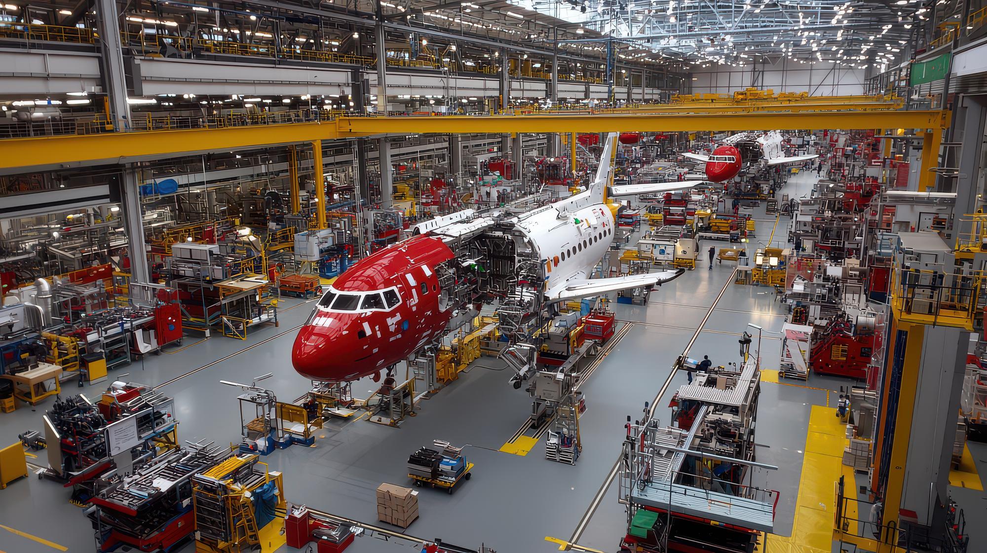
Develop complex aerospace prototypes, test hardware, tooling and assembly aids with a manufacturing route matched to the programme stage. Excel Rapidtech provides industrial 3D printing, CNC machining, vacuum casting, reverse engineering and post-processing for engineering teams that need physical parts for evaluation before committing to production.
Send your CAD model, drawing, quantity and test conditions for an aerospace prototype manufacturability review.
What is aerospace rapid prototyping?
Aerospace rapid prototyping is the controlled manufacture of physical aircraft, spacecraft, UAV or ground-support components for design learning, fit verification, aerodynamic study, assembly planning, functional testing or low-volume development. Parts may be polymer or metal and may be produced additively, machined, cast or assembled through a hybrid process.
Aerospace programmes place unusual demands on prototype decisions. Weight, packaging, temperature, fluid exposure, vibration, surface condition and traceability may all influence the chosen route. A wind-tunnel model and a flight-intent component are not equivalent, even when they share the same geometry. The first step is therefore to define what the prototype must prove and what it is explicitly not approved to do.
NASA notes that additive manufacturing can enable new designs and reduce the schedule burden of complex development hardware, while also emphasising that safe implementation requires disciplined qualification and production controls. See NASA’s overview of additive manufacturing standards for human spaceflight. For commercial projects, the same principle is useful: design freedom creates value only when material, process, inspection and intended use are clearly controlled.
Aerospace products and components we can help prototype
Excel Rapidtech can support development and non-certified manufacturing requirements after reviewing geometry, material, quantity and intended use. No aerospace approval, flight worthiness or certification should be inferred from the manufacture of a prototype alone.
UAV and drone airframe components
Unmanned aerial systems often require lightweight structures, compact packaging and frequent design changes. Candidate parts include payload housings, sensor mounts, camera brackets, antenna covers, fairings, landing-gear concepts, battery trays, electronics enclosures, ducts and cable-management features. SLS or MJF may suit durable polymer development parts, while CNC machining may suit structural metal or engineering-plastic components. The customer must determine whether a part is appropriate for ground testing or flight use.
Cabin, interior and human-interface parts
Rapid prototypes help teams evaluate ergonomics, appearance, access and assembly. Examples include control-panel mock-ups, air-vent components, light housings, seat accessories, latches, bezels, knobs and service-access covers. SLA and DLP can produce detailed visual parts, while vacuum casting can create a small group of similar samples for stakeholder review or installation trials.
Ducts, manifolds and fluid-routing concepts
Additive manufacturing is valuable when a design contains curved routes, branching passages or space-constrained geometry. Polymer ducts and manifold concepts can support packaging, assembly and low-pressure evaluation. Metal additive manufacturing may be reviewed for complex metal concepts. Pressure, temperature, fluid compatibility and safety requirements must be disclosed because a geometric model is not automatically a qualified fluid component.
Brackets, mounts and lightweight structures
Topology studies and packaging constraints often produce organic bracket forms. A rapid prototype can confirm accessibility, clearances, fastener positions and installation sequence before a production route is finalised. Depending on the test, a bracket may be printed as a polymer fit-check, CNC machined from a specified metal, or additively produced in metal for further engineering evaluation.
Test models and research hardware
Aerospace R&D teams may require scale models, wind-tunnel components, sensor holders, calibration fixtures, test coupons, equipment housings and one-off experimental hardware. These projects benefit from clear datum definitions, repeatable mounting features and documentation of any post-processing that may influence the result.
Manufacturing jigs and fixtures
Drill guides, assembly locators, checking fixtures, trim templates, protective tooling, bond fixtures and ergonomic aids can shorten development cycles without becoming part of the aircraft. Polymer additive manufacturing can reduce weight for operator-handled tools, while CNC machining can support durable datum features. Inserts or wear surfaces can be incorporated when the use case requires them.
Legacy-part and maintenance development
Reverse engineering may help recover geometry for an obsolete cover, duct, tool or non-critical component when authorised CAD data is unavailable. The workflow must consider wear on the source part, inaccessible surfaces, original material, configuration control and ownership rights. Recreating geometry does not establish airworthiness or permission to install the reproduced item.
Aerospace manufacturing services from Excel Rapidtech
| Service | Engineering value | Example aerospace uses |
|---|---|---|
| SLA 3D printing | Fine details and smooth visual surfaces | Cabin concepts, instrument bezels and display models |
| DLP 3D printing | Detailed small resin components | Switch features, small housings and presentation parts |
| SLS 3D printing | Support-free complex nylon geometry | Ducts, UAV housings, clips, brackets and tool bodies |
| MJF 3D printing | Durable nylon prototypes and repeated parts | Enclosures, mounts, fixtures and assembly aids |
| Metal 3D printing | Complex metal geometry for development | Lightweight concepts, compact manifolds and specialised hardware |
| CNC machining | Controlled features in machinable plastics and metals | Plates, structural prototypes, mounts, housings and test hardware |
| Vacuum casting | Small batches based on a finished master | Interior samples, flexible covers and repeated appearance parts |
| Reverse engineering | Recovering authorised geometry from a physical item | Legacy tools, covers, ducts and maintenance aids |
| Post-processing | Surface preparation and presentation | Painting, joining, surface treatment and screen printing |
How to select the right process
Use additive manufacturing for geometric freedom and rapid iteration
SLA, DLP, SLS, MJF and metal additive manufacturing each solve different problems. Resin processes can favour detail and appearance. Powder-based polymer processes can support complex functional nylon parts. Metal additive manufacturing can make shapes that are difficult to machine, but it introduces its own design, support, finishing and validation considerations. Process selection should not be based only on a material name.
Use CNC machining for specified material and precision interfaces
CNC machining is often the practical choice when a prototype must use an engineering plastic or metal closer to the planned production material. It also suits holes, sealing faces, threads, datums and mating interfaces that need controlled machining. Deep pockets, internal corners, tool reach and workholding should be reviewed early.
Use vacuum casting for repeated polymer appearance samples
Vacuum casting can reproduce a refined master in a small batch. It is useful for cabin samples, covers, gaskets and presentation assemblies when tooling for conventional moulding is premature. Cast polyurethane properties are application-specific and should not be described as identical to a nominated production thermoplastic without supporting data.
Combine processes when one method cannot answer every requirement
A printed duct may receive machined interfaces. A detailed master may be printed, finished and vacuum cast. A large model may be divided, joined and painted. An assembly may combine a CNC metal frame with polymer covers. Hybrid manufacturing is often more practical than forcing every feature into one process.
From CAD data to an evaluated aerospace prototype
Define the programme stage
State whether the requirement is for a concept model, packaging check, ground test, aerodynamic study, tool, fixture, development assembly or potential end-use evaluation. Identify whether any part will see flight, pressure, heat, fuel, hydraulic fluid, UV, vibration or load.
Establish critical requirements
Supply 3D geometry plus a controlled drawing for datums, tolerances, interfaces and inspection points. Mark critical-to-function characteristics. Include the configuration or revision identifier so that manufactured parts can be related to the correct design state.
Review design for manufacturing
Excel Rapidtech can review wall thickness, overhangs, trapped volumes, tool access, build direction, support removal, joining, finishing and inspection access. Recommendations may include splitting an assembly, changing a local radius, adding machining stock or moving a non-critical feature.
Agree the manufacturing and finishing route
The quotation should define process, material, quantity, finish and any agreed documentation. Where customer-supplied specifications apply, they should be shared before manufacture rather than after the parts are complete.
Evaluate and control the next iteration
Record what the prototype demonstrated, any deviations and the required design changes. If the part moves toward higher-risk testing, the validation plan and manufacturing controls should increase accordingly. Rapid does not mean uncontrolled.
Information aerospace buyers should include in an RFQ
- STEP or another suitable 3D CAD format, with a revision identifier.
- Dimensioned drawing for critical interfaces, tolerances and datums.
- Quantity for the current build and likely repeat demand.
- Intended use and explicit test environment.
- Required material properties rather than only a trade name where possible.
- Surface condition, coating, colour, marking and cleanliness expectations.
- Inserts, threads, joining and assembly requirements.
- Inspection points and required reports, if any.
- Packaging, confidentiality and data-handling requirements.
- Whether the part is a model, tool, ground-test article or candidate flight item.
Clear input allows the supplier to separate cosmetic requirements from functional ones. It also reduces the risk that an assumption about material, orientation or finishing changes the engineering meaning of the part.
Quality, documentation and responsible claims
Aerospace procurement depends on evidence. A landing page should never substitute marketing language for programme requirements. Excel Rapidtech should publish only certifications, calibrated inspection capabilities, material traceability, quality-system information and customer approvals that can be documented. Where a capability is project-dependent, the page should say so.
Prototype acceptance should be based on the agreed drawing, material and inspection plan. If a customer requires certificates, first-article documentation, controlled processes or special packaging, those requirements must be evaluated before order confirmation. Manufacturing a geometry successfully does not certify the design, material system or aircraft application.
Why choose Excel Rapidtech for aerospace development work?
Excel Rapidtech operates an in-house rapid prototyping and manufacturing facility in New Delhi. Its published machine information gives aerospace engineers concrete design boundaries for early supplier evaluation. The E Plus A800 SLA platform provides an 800 × 800 × 550 mm build envelope at a stated 100-micron layer thickness for large visual models, cabin studies and master patterns. The EOS P396E SLS platform provides a 340 × 340 × 600 mm envelope at a stated 120-micron layer thickness for suitable complex nylon components.
Published SLS choices include PA12, 30% glass-filled PA12 and black PA11. These offer different stiffness and impact behaviour, so selection should follow the load case and supplier datasheet rather than the word “nylon.” Excel Rapidtech also documents a vacuum-casting capacity of up to 1000 × 700 × 650 mm for suitable repeated polymer parts. See the current Excel Rapidtech infrastructure and material details.
This multi-process capability is useful because a detailed instrument model, durable UAV housing, machined test plate and short batch of cabin samples should not receive the same recommendation. Reverse engineering and post-processing extend support beyond raw manufacture. Aerospace qualification is still programme-specific; installed equipment establishes capability, not airworthiness or customer approval.
Frequently asked questions
Can Excel Rapidtech manufacture flight-ready aerospace parts?
Manufacture alone does not establish flight readiness. Excel Rapidtech can review aerospace prototypes and development components, but the design authority and customer must define qualification, inspection, certification and airworthiness requirements. Any potential flight application requires project-specific review and documented approval before manufacture.
Which 3D printing process is best for aerospace prototypes?
The best process depends on purpose. SLA or DLP may suit detailed visual models. SLS or MJF may suit complex nylon ducts, housings or fixtures. Metal additive manufacturing may suit a complex metal development geometry. CNC machining may be better when material condition, tolerances or machined interfaces dominate.
Can you produce aerospace jigs and fixtures?
Yes, subject to design review. Candidate products include drill guides, assembly locators, checking fixtures, sensor mounts, trim templates and protective tooling. Load, wear, temperature, chemical exposure and required datum accuracy determine whether a printed polymer, machined material or hybrid construction is appropriate.
Can you reverse engineer an obsolete aircraft component?
Excel Rapidtech can review authorised reverse-engineering requirements. The workflow must account for wear, hidden geometry, source-part condition, material and configuration control. The customer must have the right to reproduce the item and remains responsible for any approval required before installation or use.
What files should be supplied for quotation?
Provide a 3D CAD file, controlled drawing, quantity, intended use, material requirements, finish, critical dimensions and test conditions. For assemblies, include mating geometry or interface information. A clear revision identifier helps prevent manufacture from superseded data.
Can several manufacturing processes be combined?
Yes. Printed parts can be machined at selected interfaces, joined into larger assemblies or finished for presentation. A printed master can be used for vacuum casting. Hybrid routes are recommended when they answer the engineering requirement more effectively than a single process.
Request an aerospace prototype review
Share the design question before choosing the technology. Send Excel Rapidtech your CAD data, controlled drawing, quantity, material needs, intended environment and programme stage. The team can recommend an appropriate route for a model, development component, test article, jig or fixture.
Primary CTA: Upload Your Aerospace CAD File Secondary CTA: Discuss the Manufacturing Route